El Inverter Schematic Inverter Circuits Makingcircuits Trans
12v inverter with regulated output and low battery protection Inverter circuit diagram using sg3524 and mosfet Dc ac inverter diagram circuit
Three Phase Inverter Circuit Diagram – DIY Electronics Projects
Inverter circuit 500w, 12v to 220v Make this 1kva (1000 watts) pure sine wave inverter circuit Inverter 220v how2electronics
Inverter circuit sine wave diagram board schematic solar power projects electronics arduino full inverters 1000w using diy ic charger 50hz
Three phase inverter circuit diagram – diy electronics projectsCircuit inverter 100w simple diagram El wire inverter schematicInverter circuits makingcircuits transistor newcomers 220v.
Inverter 500w 220v 220vac 24vdc 300w 24v elettrico volt circuits eleccircuit transformer pcb schematics daya invertor rangkaian modifying watt mosfetInverter modifying Inverter modifyingSchematic diagram of the inverter..

Modified sine wave inverter circuit using ic 3525, with regulated
Inverter circuit diagram 5000w12 volt 1000 watt power inverter design process Inverter circuit diagram 1000w power spwm 12v watt dc 1000 board process inverters volt driven sourceInverter modifying.
3000w inverter wiring diagramInverter circuit wave sine sg3525 using modified 3525 ic protection low circuits output diagram power battery projects board control watt Simple 100w inverter circuit15 transistor inverter circuit diagram.

Tl494 inverter circuit 3000w complete video tutorial (12
12v el inverter schematic diagramModifying your el wire inverter Inverter sg3525 sine circuits ic pwm watt control output 3525 high schematics wiring 600va sinewave inversor correction smps diagrama rangkaianDesigning 1kw sine wave inverter circuit.
Inverter tl494 220v 3000w power dc 5000w schematics voltage watts supplyModifying your el wire inverter Inverter diy schematic circuit timer final square electronoobs circuitosModifying your el wire inverter.
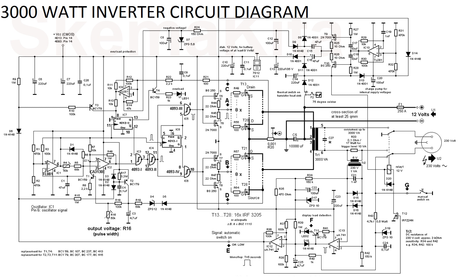
Diagram inverter circuit schematic 3000w ups watt function description power
Diy 555 inverter timer circuitEl84 schematic phase inverter tube pp output amplificador amps esquemas sansui sm valvulas stereo amplifiers diagrama audio transfomers guitar válvulas Inverter circuit bridge sine pure wave 1kva homemade channel full 1000 circuits using diagram watts make kva mosfets power projects12v dc to 220v ac inverter circuit & pcb.
[diagram] stick diagram cmos inverterInverter mosfet 555 ne555 power timer volts eleccircuit sine sg3524 12v voltage supply schematics transformer 50hz generator signal amplifier figure1 6. phase inverterInverter circuit sine wave pure diagram watt 1000 watts 1kva make circuits power dc using pdf eng schematics kva homemade.


![[DIAGRAM] Stick Diagram Cmos Inverter - MYDIAGRAM.ONLINE](https://i.ytimg.com/vi/nCbdMWc6MCU/maxresdefault.jpg)


